


In 2012 the Asphalt Institute, in cooperation with the Federal Highway Administration (FHWA), rolled out research findings concerning longitudinal joint density. The results were presented to over 40 DOTs in the U.S. and the recommendations were adopted in whole or in part by many.
The increased focus on longitudinal joints led one Kansas asphalt superintendent to take a deep dive into what is going on behind his pavers. Ross Weber of APAC-Sheers in Hutchinson, Kansas, has spent over 40 years in the industry and was committed to studying premature joint failures.
As he and one of his select paving crews studied the problem, it became evident that there were more than just joint performance issues. There are failures that are parallel to the joint that are offset from a few inches to a couple of feet. There are similar failures that commonly occur at a lateral distance of two, five and seven feet from centerline. He postulated that these distresses may be both paver- and roller-related. This article will focus on the impacts of paver screed settings on the uniformity of mat density. Other pavement distress issues will be addressed in a future article.
It all started
In the summer of 2019, APAC-Shears was working on a project on I-135 in McPherson County, Kansas and they were struggling to achieve acceptable longitudinal joint density. The normal adjustments such as raising the screed extension to get more material at the joint and give the roller a better chance of obtaining density didn’t work.
The crew was getting good overall mat density (93%+), but they just could not get the joint density up to 90 percent. Prior to paving, his crew normally set their screed using a string line, while the screed was blocked up in the air. The main screed would typically be adjusted to about 1/8” crown. However, when the screed was down and paving, they actually had a 1/4” crown in the mat when they measured behind the screed. While not excessive, it turned out to be more than was needed. It is important to understand that setting the screed while in the air or on blocks will get you in the ballpark, but these settings can change when the screed is lowered onto the pavement and again when it becomes loaded with the mix.
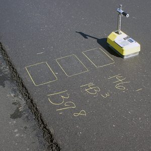
They experimented with flattening the main screed and extensions to zero crown. These settings were verified by using a 12’ straightedge to check the mat behind the screed. There was some improvement, but after taking a few extra density measurements adjacent to the longitudinal joint, it was discovered that density in the wheel path was very low. The density technician went back and tested the previous day’s run and found the density in the inside wheel path was lower when compared to the rest of the mat. These areas of low density had gone unnoticed because few of the random test locations fell in the inside wheel path and the densities outside of the wheel path were extremely high. This brought the average density high enough to meet specification requirements, but with a high standard deviation. It is important to note that this pavement was being placed on a milled surface and the low densities were not a result of preexisting rutting in the wheel path.
Making a model
Putting his decades of construction experience to work, Ross constructed a model of a screed that would bend, rise and lower just like the screed they were using in the field. His major focus was on how screed settings can direct the flow of material under the screed – which creates areas that have higher density as the material exits under the tail of the screed. These areas “with too much mix” end up creating an imperceptible high spot.
Hydraulic extension screeds are a great convenience. However, they can also create many headaches that can go undetected. If there is crown in the main screed, the operator almost always compensates for it by sloping the centerline extension. This creates a series of peaks and valleys that are impossible to compact adequately.
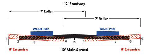
With his model, Ross readily detected nine major locations along the screed where high or low spots can be created by the paver in the yet-to-be compacted mat. If not identified, these high and low areas create bands of varying density that may run the entire length of a project.
“It is important to identify the high spots and then why they are high. If a cold joint is matched too tight this will create a high spot, the interface between the outside edge of the main screed and the extension screed can create a high spot. The interface of the main screed and the inside edge of the extension can create a high spot. If the center of the main screed has crown, it creates a high spot. The same goes for the other half of the screed. Anywhere an out-of-adjustment screed creates a high spot there will be a corresponding low spot,” said Ross.
“The screed extensions need to have enough evenly applied down pressure to uniformly finish all of the surface passing below them, both longitudinally and transversely. The density under the main screed between the screed extensions is often higher or lower than under the extensions. The density under the main screed is adjusted by raising or lowering the extensions. Lowering the screed extensions decreases density in the center of the main screed. Raising the screed extensions increases density under the main screed section. This is what causes a mat texture to shine more in the middle or outer edges of the mat. Minor adjustments can be made by changing the center crown of the main screed. A screed may even need negative crown (in the air) for it to flatten out when lowered. The ultimate goal is to always be as flat as possible after rolling, with uniform density,” added Ross.
Adjustments
After concentrating on getting the main screed and extensions aligned, the APAC-Sheers crew started each day, and any time the screed was picked up, by using a 12-foot straightedge on the mat to assure it was still flat. They then ran a transverse density profile every 12” across the pavement lane and evaluated the data. The crew would make screed adjustments where necessary and then run another transverse density profile. This process was repeated until the desired results were achieved. In the early stages of their field trials, they profiled the road every hour or more. In the beginning, it was not uncommon to see swings in unit weight as much as 5-8 pounds per cubic foot in adjacent tests.
“It is worth noting that the straight edge gets us close, but the fine adjustments are made based on the transverse profiles. This may require the screed to be adjusted to something other than zero crown,” said Ross.
The new process Ross’s team settled on starts with a transverse density profile during pre-production. If it is in the ballpark, they proceed to normal production. At the start of normal production, as soon as a section is rolled, they perform a transverse density profile and adjust the screed to eliminate highs and lows.
Remember, high density means too much asphalt and low density means too little asphalt. Repeat this process until desired results are achieved. Any time the screed is picked up throughout the day it is advisable to repeat the process. Longitudinal joint density analysis is part of this process.
Ross’s procedure for screed adjustment starts with setting the center crown of the main screed. Then matching the height on the extension screeds to the main screed and slope the extension screeds up or down to match the plane of the main screed. Next is adjusting the screed to the needed height at the cold joints. If there is a mat texture difference between the main and extension screeds, adjusting the angle of attack will achieve a uniform texture.
“For the most part, we don’t adjust the screed extension height to correct texture issues. We adjust the extension height to achieve density and if we adjust for aesthetics, we defeat the purpose of adjusting for density,” said Ross.
New procedures
“We have learned that we can’t be overly concerned with the look prior to compaction. We also learned that the best joints aren’t always the prettiest joints. The joint may be beautiful today but what will it look like in five years?”
“Our team has continued to learn over the past couple of seasons. While there are still occasional density issues, they are very good at identifying and fixing the problem. One of our crews often needed four and sometimes five rollers to achieve the required density across the mat. Now they never need more than three and sometimes as few as two,” Ross added.
“It took quite a while to understand how sensitive density is to screed settings. A roller bridging over a high spot the thickness of a quarter correlates to a reduction of four percent density in the adjacent low area. The road always rolls out and looks flat. Even when it isn’t,” said Ross.
One can only imagine the effects of other items such as leaving a portion of a windrow in-place as it passes under the paver or spillage on the roadway in front of the hopper.
Ross believes their new screed setting procedures allow the APAC-Sheers teams to prevent problems before they occur. Making corrections to the longitudinal density bands early in the day helps assure that density will be good all day. Over time the team has become more proficient at reading the mat and spotting problems visually.
“The crew that has embraced every aspect of the new process has very consistent density, with longitudinal joint densities often as good as interior mat density. The new procedure assures that our pavement density is consistently high enough that there is seldom any possibility of penalty,” said Ross.
Blow is an Asphalt Institute Senior Regional Engineer based in South Dakota.